Abstract
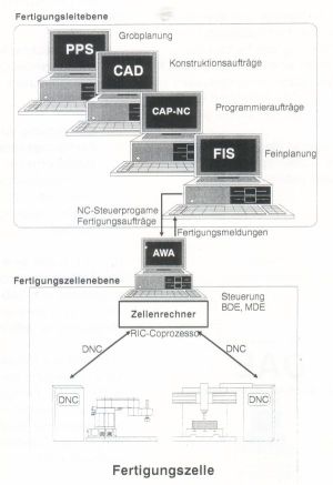
Ziel war die Realisierung einer physikalischen
Kopplung von Fertigungskompo-nenten einer Fertigungszelle mit einem
Werkstattsteuerungssystem im Rahmen der CIM-Aktivitäten an der
Technische Universität Hamburg-Harburg. Ausgangs-punkt dieses Projektes
war das neue Softwarepaket IBM DAE (Distributed Automation Edition für
OS/2). Für die Realisierung des Projektes wurden zwei wesentliche
Punkte bearbeitet:Zellenrechnerkonzept, wodurch die Anwendungsschicht
des Zellenrechners spezifiziert wurde und die Einbindung vorhandener
Fertigungskomponenten in die DAE-Software, um die Kommunikationsaspekte
der CIM-Zelle in DAE zu berücksichtigen.
Key words: CAD/CAM Systeme, CIM-Zentrum, CNC
Netze, Robotik, Maschinenprotokolle.
Abstract
The Computer-Assisted Design (CAD) and the
Computer-Assisted Manufacture (CAM) processes have been presented as
a model to ensure high flexibility and accuracy. The complexity of this
model implies a long and difficult tteaching-learning process for both
students and designers operating the tool machines. This article presents
a learner-centered project for engineering students to develop technology
by manufacturing 2D products without precision but with rapid fabrication
response using commercial computere programs and appropiate interface
adaptions.
Key words: CAD/CAM, machining,
interpolation, CNC.
Improvement of aluminium parts
machining process in a numerical control milling machine
Zambrano, P., Escamilla, I., López,
E.
International Materials research Congress 2001. Academia Mexicana de
Ciencia de Materiales, A.C., 2001.
Abstract
In processing parts by numerical
control it is very important to
optimize the machinability of these ones, this could turn out in to
higher production with good quality and low cost. To achieve this, there
are some parameters that must be taken into account, such as tooling
and workpiece materials, cutting speeds and feed rates.
A critical point becomes to determine
the feed and cutting speeds, if any of both is increased while the other
one stays constant, the machining time could be lower with the excessive
tool ware.
The aim of the present work is to obtain and improvement in the machining
process of alluminium parts by numerical control milling. The first
step was to find the optimal path by digitalized points that conduct
to this one. With the digitalized points a numericla control code was
obtained and the process variables were choosen, then an interactive
matrix was set in order to find the speeds that fulfill the best mechanical
properties and surface finishing of the work piece. Each piece was mechanically
characterized and microstructures were studied.
Key words: CAD/CAM, alluminium milling machining,
CNC code optimization.
Abstract
The evolution of CAD/CAM (computer aided design
/ computer aided manufacturing) systems has
enabled more complex parts to be modelled. Today, most of the modelled
parts are more than grouped geometric
primitives (points, arcs, lines, etc), but complex shapes defined trough
three dimension surfaces, that can
not be directly processed by the tool-machine control. Hence, there
is a need to create methods to allow the machining
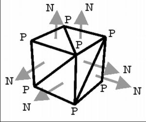
process. This article presents an approach to generate
numerical control code (NC code) from 3D meshes geometries for a 2 ½
axis milling machine. First the
theoretical constrains of 3D machining are explained. Then a method
based on mesh geometries and unit
vectors is presented. The results of this method were obtained by means
of computer simulations. Finally, a series of proposals for the improvement
the proposed method are presented.
Key words: CAD/CAM, geometric modelling machining,
interpolation, CNC.
Maquinado
de una sucesión de curvas
López, E., Colás,
R., Rall, K., Ramírez, F.
Revista Ingenierías vol. IV, no. 11, 2001.
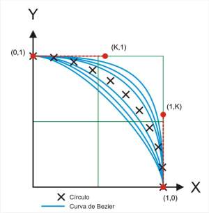
Abstract
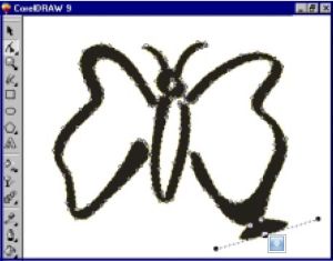
Many objects in the nature are inherently of
soft and continuous geometry, and so much the computers to model them
as well as the machines that manufacture objects starting from those
models should be able to reproduce such geometries. The computer aided
design and manufacturing systems (CAD/CAM), the high quality typography,
the artistic sketches and the movement of a cinema camera are examples
of these conditions of soft and continuous bend. A technique of modeling
faithful to the reality defines curves with different characteristic
each one whose bend follows better the contour of the object that models.
This article presents the problem of the machinning of geometries in
a plane with geometric continuity, and it proposes a solution. At the
same time reference is made to the different mathematical aspects of
the problem.
Key words: CAD/CAM, geometric modelling, Bezier,
NURBS, machining, interpolation, CNC.
Abstract
Several survey on machinability has been done,
first to understand the process, and then to optimize and improve it
under a particular criterion. In a machine-tool system, the role of
the NC-code is critical, as it concerns not only the tool paths but
also the cutting values. The optimal code is determined not only by
the machine's control, but also the geometric conditions and the materials
involved both in the tool and part to be machined.
This first article presents a method to study the relationship between
the parameters of the NC-code by means of a mathematical model. Experimental
results allowing the validation of the method are presented.
Key words: geometric modeling, machining,
machinability, CNC.
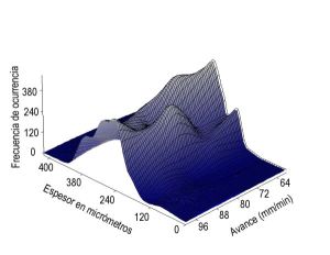
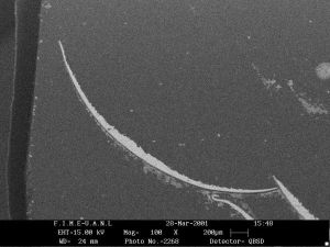
Abstract
Since the study of machinability must be done
by means of a particular criterium, the chosed for this work was the
analysis of the chip geometry. In the first article of this serie was
exposed also the mathematical model of the tool movement, and the influence
on the machined surface.
This second article presents the experimental results of the study on
the relationship between the parameters of the NC-code and chip thickness
by means of statistik. This should allow part of the validation of the
method presented in the first article .
Key words: geometric modeling, statistik,
machining, machinability, CNC.
Abstract
Requirements of high-quality standards have
become essentials in manufacturing technology. Thus, the conditions
of the process must be related with the surface finish achieved.
One of those conditions is the thermal energy generated during the machining
process. This energy can be measured in terms of temperature increments
and depends of the feed, depth of cut and tool cutting speed.
As a complement for the series of experiments exposed in the preceding
articles this work presents the theoretical fundamentals and experiments
based in the effects of tool feed on the temperature behavior during
the machining process. .
Key words: thermal energy, cutting speed,
tool feed.
Evaluación de las condiciones
de maquinado por medio de emisiones infrarrojas
López, E. Ruiz, M. Méndez,
L.
Cartel en el VII Simposio de Ciencia y Tecnología, SEP-CONACyT
2002.
Resumen
En la actualidad los procesos de maquinado
requieren de geometrías y acabados precisos que se encuentren
dentro de las normas estandarizadas. Existe un número considerable
de variables que intervienen en los procesos de manufactura, y mas específicamente
en el proceso de remoción de material. Para comprender el alcance
de estas variables es necesario tener un conocimiento cualitatuvo y
cuantitativo de los parámetros que las rigen y las posibles interacciones
entre ellos. A primera instancia, debe tenerse en cuenta las magnitudes
de energía utilizada para la remoción de material. Esta
energía está determinada por las fuerzas y velocidades
en el plano de corte.Teniendo en cuenta que de la energía utilizada
para el corte de material cerca del 98% se convierte en energía
térmica, el conocimiento de la cantidad de calor que se genera
en el proceso es determiante para poder establecer los rangos admisibles
de las variables que producen esta generación de energía.
El presente trabajo propone la metodología para determinar estos
rangos de energía durante el maquinado en términos de
temperatura, y obtener la relación que guardan con la velocidad
de corte, para encontrar los parámetros óptimos del proceso
de remoción de material.
Caracterización de
superficies maquinadas por medio de parámetros de rugosidad
López, E. Cavazos, R. Delgado,
M.
Cartel en el VII Simposio de Ciencia y Tecnología, SEP-CONACyT
2002.
Resumen
En la comprensión de los procesos que
generan superficies es crucial la relación entre la calidad de
la superficie y su comportamiento funcional. Esta comprensión
puede lograrse a través de una técnica adecuada de caracterización
y síntesis de las superficies. A continuación se plantea
una metodología que caracteriza las superficies maquinadas.
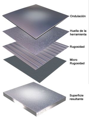
Este trabajo centra su base en caracterizar la superficie maquinada
identificando las componentes de la huella de la herramienta y las características
de rugosidad asociadas a las propiedades del material al ser maquinado.
Caracterización de
superficies maquinadas por medio de parámetros de rugosidad
López, E. Ruiz, M. Delgado, M.
Foro de Investigación UDEM 2002.
Resumen
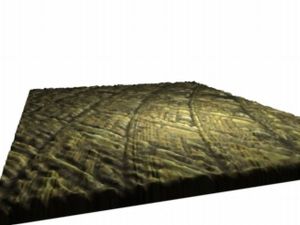
Las superficies de maquinado generadas por
medio de los procesos de arranque de viruta exhiben características
topográficas que juegan un papel fundamental en el desempeño
de la funcionalidad del producto, y pueden estar determinadas por la
fricción, lubricación, estética, etc.
Algunos de los comportamientos funcionales de la calidad de las superficies
maquinadas pueden lograrse solamente bajo su caracterización.
Los métodos para analizar superficies se basan en su caracterización
por medio de medidas tradicionales (altura promedio, distancia de pico
a pico máxima, etc), por medio de transformaciones matemáticas
(onduletas o "wavelets", análisis de frecuencia, etc) y geometría
de fractales, entre otros. La caracterización en el dominio de
la frecuencia se logra utilizando un análisis en espacio para
posteriormente transformar las características en el dominio
de la frecuencia.
Una vez conseguido esto, es posible: 1)encontrar la influencia directa
de los parámetros de corte en la calidad superficial 2)mejorar
los valores de corte 3)encontrar eventuales fallas de maquinado como
vibraciones, sujeciones, etc., para una situación de maquinado
dada.
Palabras clave: rugosidad, calidad superficial,
maquinado, método de espectro de frecuencias.
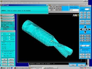
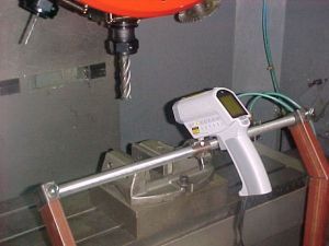
Abstract
One of the conditions in the machining process
is the thermal energy generated during the process. This energy can
be measured in terms of temperature increments and depends on the feed,
depth of cut and tool cutting speed. This work presents a finite-element
simulation based on experiments on the effects of tool feed over the
temperature behavior during the milling process.
Key words: FEM, temperature, infrared sensors,
machining, milling.
Abstract
The proper functioning of a machined part is
to a large extend dependent on the quality of its surface. The term
"surface quality'' includes not only the dimensional qualities of the
surface, but also the material properties, as hardness, color, and metallurgical
structure. The dimensional quality having to do with the surface irregularities
is known as the "roughness surface". The importance of the roughness
of the final finish has long been appreciate. The urgent need for high
production and low cost has developed techniques in wich roughness control
is of proven importance not only in the finished piece but on the intermediate
finishes as well. This work presents a result of a experiments series
based in the relationship between the feed rate and the roughness measured
in material's machined cut.
Key words: roughness, surface, machining.
Caracterización de
superficies maquinadas por medio de parámetros de rugosidad
López, E., Flores, R., Delgado,
M., Ruiz, M.
Cartel en XXIII Congreso Nacional de la Sociedad de Superficies y Vacío,
Ago. 2003.
Resumen
En la comprensión de los procesos que
generan superficies es crucial la relación entre la calidad de
la superficie y su comportamiento funcional. Esta comprensión
puede lograrse a través de una técnica adecuada de caracterización
y síntesis de las superficies. A continuación se plantea
una metodología que caracteriza las superficies maquinadas.
Este trabajo centra su base en caracterizar la superficie maquinada
identificando las componentes de la huella de la herramienta y las características
de rugosidad asociadas a las propiedades del material al ser maquinado.
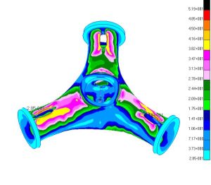
Abstract
The geometries created by the nature are often
used as base in the computer geometric modeling and they are applied
in areas like biomechanics. Other natural behaviors are support the
engineers to find better designs that have improved functionality. This
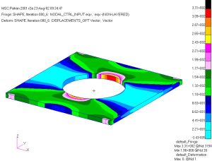
work presents the use of algorithms of biological growth embed in a
finite element environment in order to modify the shape of foundry pieces,
minimizing their maximal stress. Initially the analysis of the shape
using the method of conventional finite element is presented. Later
the same geometries are optimized with algorithms of biological growth.
Finally the results of both cases are compared.
Key words: Finite element, bio-design, notch
stress, biological growth, shape optimization, B-Splines.
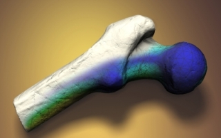
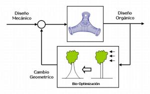
Resumen
En el diseño de componentes mecánicos
se encuentran frecuentemente cambios de geometría no uniformes
que junto con las inclusiones y defectos dentro de los materiales pueden
dar lugar a un incremento en el valor de los esfuerzos. La distribución
de estos esfuerzos en piezas con geometría compleja se puede
predecir y es deseable optimizar las zonas en donde estos se concentran.
Este trabajo presenta el uso de algoritmos de crecimiento biológico
en un ambiente de elemento finito para modificar geometrías modeladas
con matemática de superficies libres y curvas splines para poder
alcanzar la distribución uniforme y optimizada de esfuerzos que
se encuentra en la naturaleza. Convirtiendo así al diseño
mecánico en un "diseño biológico".
Palabras clave: elemento finito, crecimiento
biológico, concentración de esfuerzos, superficies libres,
optimización de la forma.
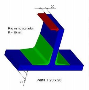
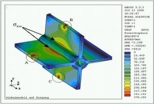
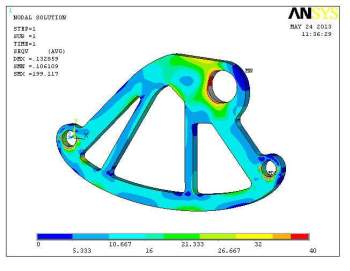
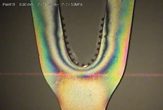
Abstract
In the production of machines, the mechanical
design of their structures must have as the highest priority the functional
needs. If the material of the component has been previously determinated,
the geometry is conditioned by an adequate stress distribution. This
work presents a geometric optimization method for a T union used in
a machine structure. The union was analyzed under a load situation with
a finite element system. A new shape was found with a optimal stress
distribution with a biological growth optimization criteria.
Key words:Finite element, bio-design, notch
stress, biological growth, free form surfaces, shape optimization.
Abstract
The surface characteristics of a machining
part in the functional performance of it have a great effect. In the
case of elements of mechanisms the surface influences in the behavior
of the parts in contact, while in the case of injection molds, this
influence is not only present in the aesthetic appearance of the final
product, but rather it can be decisive in phases of the manufacturing
process. In previous works [LOP01, LOP02a, LOP02b, LOP03] roughness
analysis of frequency has been presented to determine the influence
of the machining parameters in the surface of products, and factors
have been identified of having of direct influence in the superficial
quality. This work presents a method to model surfaces based on layers,
using to generate each layer the most significant values from the ruggedness
in different ranges, in such a way that is possible to produce synthetic
surfaces and with it is expected to predict characteristic of surface
for machining situations given.
Keywords: roughness, spectrum
of frequencies, modeling of surfaces, free surfaces, form optimization.
Abstract
The design of machines normally involves structural
members with non uniform cross sections that added to material internal
defects might cause an increase in stress concentrations. This work
presents a geometric optimization method for a flat bar with a transverse
hole in tension. The flat bar was analysed under a load situation with
a finite element system. A new shape was found with an optimal stress
distribution with a biological growth optimization criteria.
Keywords: Finite element, bio-design,
notch stress, biological growth, design of machines, shape optimization.
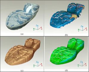
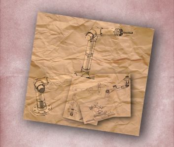
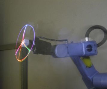
Abstract
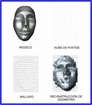
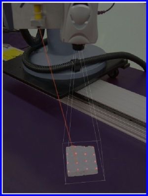
The 3D scanning has become an useful tool in
the development of products because of the increasing use of reverse
engineering techniques. It has many advantages related to reducing time
and costs with a good accuracy level. This
document presents a system to reproduce 3D geometries from images captured
with a measuring instrument based on a digital camera and a laser pointer,
manipulated through a robot arm. This work includes the calibration
of the measuring instrument and the reconstructed surface of the object
in 3D coordinates.
Keywords: 3D scanner, measuring
by triangulation, reverse engineering, error estimation, 3D reconstruction.
Abstract
The 3D scanning has become an useful tool in
the development of products because of the increasing use of reverse
engineering techniques. It has many advantages related to reducing time
and costs with a good accuracy level. This
document presents a system to reproduce 3D geometries from images captured
with a measuring instrument based on a digital camera and a laser pointer,
manipulated through a robot arm. This work includes the calibration
of the measuring instrument and the reconstructed surface of the object
in 3D coordinates.
Keywords: 3D scanner, measuring
by triangulation, reverse engineering, error estimation, 3D reconstruction.
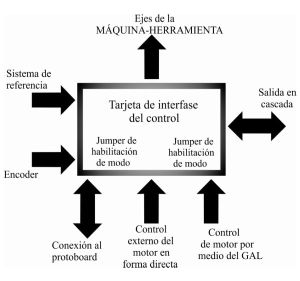
Abstract
The versatility of a machine-tool is directly
influenced by the mechanical construction, the user-machine interaction
and its control. These features are only determined by the fabricant
making it impossible for the user to achieve complex applications that
require some type of additional
funcionality from the machine. the present works presents the design
and implementatin of an open structurecontrol able to adapt to different
user needs. The technological implementation is based on a system conformed
by a Motorola MEV912B32 micromodule and an own control interface based
on state changing devices based on operation frecuencies. The development
includes the verification of the systems constants for the implementation
of a command system that allows the input of commands from differents
devices. The position, velocity and performance test results indicate
that the control is linear and allos knowing the operation range.
Keywords: Tool-machine, step
motor control, open structure, machining, microcontroller.
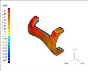
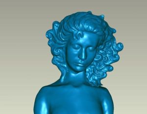
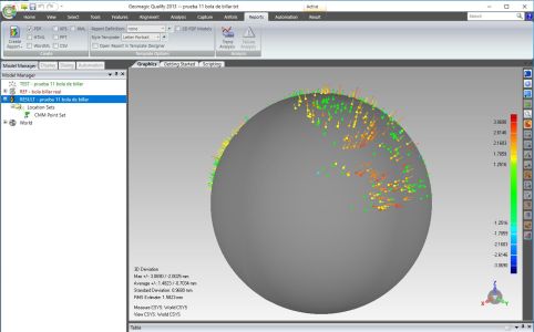
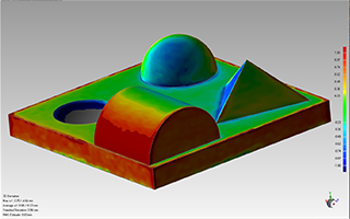
Abstract
Rapid prototyping
(RP) has become a useful tool in product design. It allows to test the
product geometry before the model is turned to the production. Different
technologies exist, each with advantages like speed, precision, color
fidelity, material cost or some basic mechanical properties.This work
presents the evaluation of the geometrical and color properties of the
prototypes from a RP machine.
This evaluation was done with a coordinate-measuring machine (CMM).
The results show the construct deviation, allowing the error correction
before the model was sent to build.
Keywords: rapid prototyping,
3D scanninggeometric desviation, color analysis, spectrocolorimetry,
reverse engineering, error estimation.
|